When replacing or validating a small C0G/NPO ceramic like the GMT10CG9R1B50NT4 capacitor, tight capacitance tolerance and predictable temperature/DC-bias behavior determine success in RF, timing and precision circuits. Point: engineers consult focused part guides for reproducible qualification; Evidence: part-specific behavior dominates filter and oscillator stability; Explanation: this article summarizes specs, test procedures, and cross-reference guidance to shorten qualification time.
Background — Part at a glance: what the GMT10CG9R1B50NT4 capacitor is
Point: identify the single-line summary from the official datasheet; Evidence: the datasheet lists nominal capacitance, tolerance, rated voltage, dielectric (C0G/NPO), package code and temperature range; Explanation: extract those fields from the ordering table, electrical characteristics and mechanical drawing to form the procurement and test baseline for the GMT10CG9R1B50NT4 capacitor.
What to pull from the official datasheet
Point: capture only documented figures; Evidence: ordering-code tables and electrical-characteristics sections contain the authoritative numbers for capacitance, tolerance and voltage rating; Explanation: do not assume values—quote the datasheet fields verbatim in procurement specs and test reports to avoid substitution errors during qualification.
Typical applications and why this part is chosen
Point: C0G/NPO ceramics are preferred where stability matters; Evidence: designers pick these parts for RF front ends, timing networks and precision filters because of low loss and minimal temperature drift; Explanation: target readers—hardware engineers, buyers and test technicians—should map application constraints (stability, low DF, predictable bias shift) to the part selection checklist.
Data Analysis — Datasheet specs broken down for practical use
Core electrical specs: capacitance, tolerance, voltage & temperature ratings
Point: interpret nominal capacitance and tolerance for margins; Evidence: tolerance expressed as ± value determines usable capacitance range at reference conditions; Explanation: translate tolerance into worst-case circuit margins, compare rated voltage with expected DC-bias in-circuit, and plan verification tests to confirm datasheet-stated behavior under operating conditions.
| Parameter | Datasheet Value | Engineering Notes |
|---|---|---|
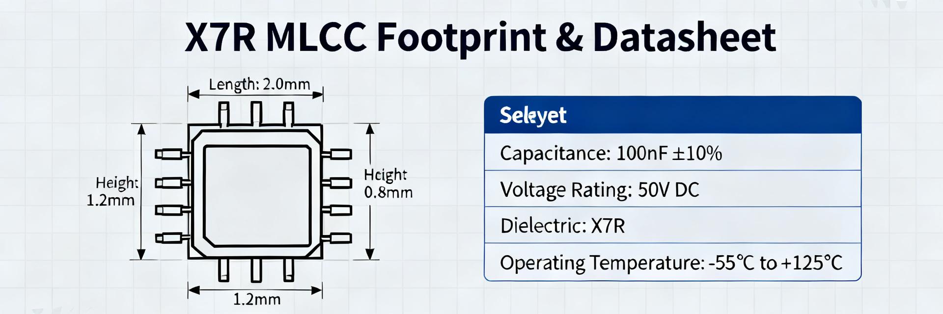
| Nominal Capacitance | 9.1 pF | Measured at 1.0 ± 0.2 Vrms, 1.0 MHz ± 10% |
| Capacitance Tolerance | ±0.1 pF (Code B) | Tight tolerance envelope for precision RF filtering |
| Rated Voltage | 50 VDC | Operate with suitable margins in critical circuits |
| Dielectric Type | C0G (NP0) | Class 1, ultra-stable, zero DC bias drift |
| Temperature Range | -55°C to +125°C | Linear temp coefficient: 0 ± 30 ppm/°C |
| Package Footprint | 0402 (1005 Metric) | Ultra-small package minimizes parasitic inductance |
Secondary electrical parameters: ESR/ESL, dissipation factor and stability
Point: assess parasitics for high-frequency or pulse use; Evidence: ESR, ESL and dissipation-factor lines indicate frequency-dependent loss and resonance behavior in datasheets; Explanation: use those parameters to predict insertion loss and transient response, and prioritize samples for impedance analysis when RF or fast-edge signals are present.
Data Analysis — Test data & real-world performance
Recommended test matrix and expected reference measurements
Point: define repeatable measurements for verification; Evidence: standard tests include LCR measurements at 1 kHz and 1 MHz, DC-bias sweeps (0 V to rated V), temperature sweeps across the datasheet range, and leakage checks; Explanation: log sample ID, frequency, DC bias, temperature, C and ESR to detect out-of-spec lots and to compare against datasheet tolerance bands.
Failure modes, long-term reliability & derating considerations
Point: list common sources of part variation and failure; Evidence: mechanical cracking from board flex, soldering thermal stress, and bias-induced capacitance shifts are documented root causes in reliability studies; Explanation: apply conservative derating, perform accelerated life tests, and track lot codes to estimate field reliability for long-life systems.
Method Guide — How to test and validate the GMT10CG9R1B50NT4 on your bench
Step-by-step test procedures and instruments
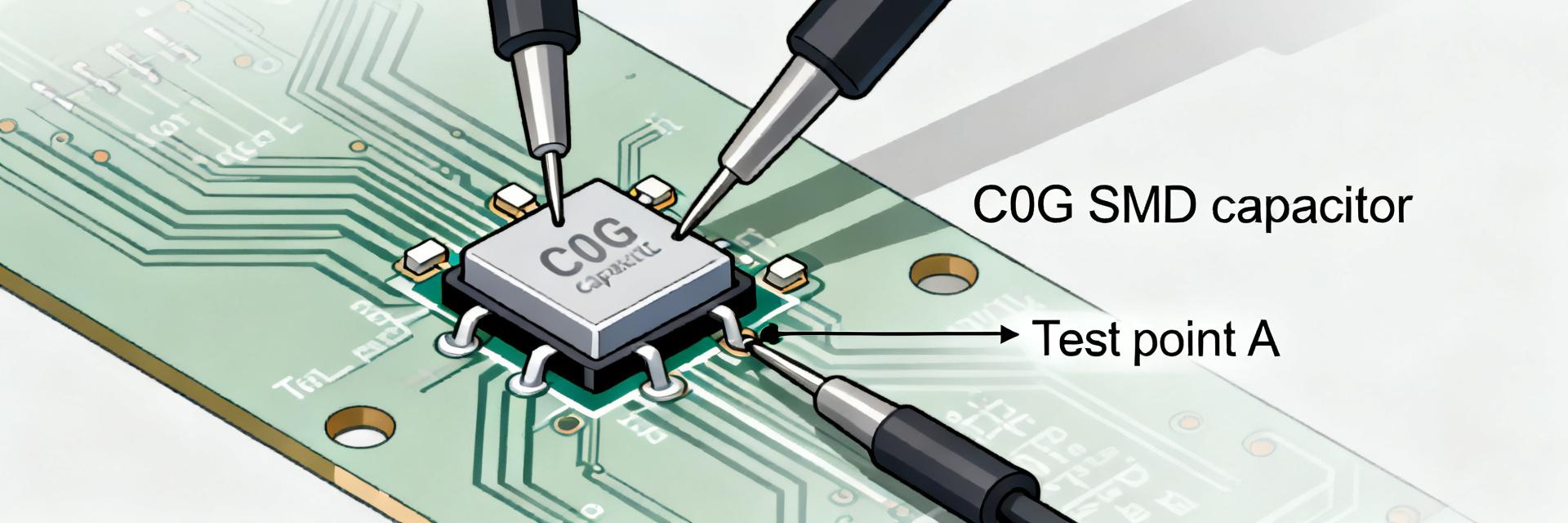
Point: choose the right instruments and fixtures; Evidence: a precision LCR meter or impedance analyzer, temperature chamber, DC bias source and calibrated SMD fixtures are required for characterizing small ceramics; Explanation: run capacitance vs. DC-bias and temperature characterizations at 1 kHz/1 MHz, perform open/short/load calibrations, and document test settings for reproducibility.
Interpreting results and troubleshooting measurement discrepancies
Point: separate measurement artifact from real part behavior; Evidence: fixture parasitics, calibration drift and mechanical stress often explain outliers; Explanation: use witness samples, repeat measurements with alternative fixtures, and request manufacturer lot test reports when deviations exceed tolerance to determine whether parts or measurement setup are at fault.
Cross-reference & Sourcing — Finding equivalents and verified replacements
What must match when cross-referencing (hard constraints vs. negotiable attributes)
Point: establish non-negotiable attributes for equivalents; Evidence: nominal capacitance and tolerance, dielectric (C0G/NPO), rated voltage, package/footprint and temperature range must align for functional interchange; Explanation: maintain a rapid-screen checklist distinguishing hard matches from flexible attributes like termination finish or ESR/ESL that can be validated by sample testing.
Using cross-reference tools and verification checklist before qualification
Point: follow a structured workflow for replacements; Evidence: practical steps include searching by footprint, filtering by dielectric/voltage/tolerance, verifying mechanical drawings and requesting sample test data; Explanation: collect datasheets, lot codes and sample measurements, then record pass/fail results and traceability before approving a substitute for production use.
Actionable Recommendations — Design, procurement and lifecycle best practices
PCB and assembly notes for reliable use
Point: protect the part from assembly and mechanical stress; Evidence: recommended footprint geometry, solder fillet control and controlled reflow profiles in application notes reduce cracking risk; Explanation: avoid tight fillets, limit board flex near the component, and follow manufacturer soldering recommendations to preserve capacitance stability in precision layouts.
Procurement, stocking and obsolescence mitigation
Point: set procurement rules to avoid surprises; Evidence: require lot traceability, sample qualification and minimum order quantities from suppliers when sourcing long-life components; Explanation: maintain safety stock, plan last-time buys for legacy designs, and write purchase specifications that force required attributes (capacitance, tolerance, dielectric, operating temperature and compliance) into vendor contracts.
Summary
- Read the official datasheet fields first and record nominal capacitance, tolerance, voltage and dielectric—this anchors all verification steps for the GMT10CG9R1B50NT4 capacitor and prevents substitution mistakes.
- Run a reproducible test matrix (1 kHz/1 MHz, DC-bias sweep, temperature points) with calibrated fixtures and log results to spot lot variation and bias-induced shifts before qualification.
- Cross-reference only to parts that match hard constraints (capacitance/tolerance, C0G dielectric, rated voltage, footprint); collect datasheets, lot codes and sample test data prior to approval.
Frequently Asked Questions
How should I verify capacitance vs DC bias for this capacitor?
Measure nominal capacitance at a 1 MHz reference frequency (with ≤1.0 Vrms signal drive), then systematically apply incremental DC bias up to the 50V rated limit. Map the resulting capacitance and ESR values to monitor deviations. Note that because this component utilizes an ultra-stable Class 1 C0G/NP0 dielectric, the capacitance shift under bias will remain functionally negligible, maintaining near-zero drift.
What test equipment and fixturing are essential for small C0G parts?
Characterizing sub-10 pF capacitors demands a high-precision LCR meter or impedance analyzer operating at 1 MHz, paired with a specialized low-loss, shielded SMD test fixture. Full open, short, and high-frequency load compensations must be successfully executed directly at the terminal plane to strip out parasitic fixture capacitance and stray lead inductance from the measurement path.
When is a cross-reference acceptable without full qualification?
Unqualified substitutions should only be considered for non-critical, generic decoupling loops. For sensitive RF tuning, precise timing circuits, or high-Q filtering networks, any proposed alternative must undergo a structured bench qualification to thoroughly evaluate equivalent series resistance (ESR), self-resonant frequency (SRF), and mechanical tolerances before production approval.
What are the primary failure modes and reliability concerns for GMT10CG9R1B50NT4?
The primary threat to small-footprint MLCCs is mechanical stress cracking induced by excessive PCB flexure, thermal shocks from manual soldering iron contact, or poor reflow cooling rates. To safeguard high reliability, maintain tight PCB board deflection limits and strictly adhere to the manufacturer's specified reflow profiles.