AANI-FB-0174-1 FPC Antenna: Measured Band Performance

2026-02-05 62

Measured S11, realized gain, and efficiency reveal distinct performance regions across the device’s cellular bands. This report summarizes performance highlights, test methodologies, and integration guidance for field validation.

Product Overview & Band Mapping

AANI-FB-0174-1 FPC Antenna Lab Testing

Technical Specifications

The AANI-FB-0174-1 is a precision-engineered flexible printed circuit (FPC) antenna optimized for cellular and IoT ecosystems. It targets mid-band frequencies with a compact form factor ideal for edge-mounted integration.

Parameter Typical Value
Part Number AANI-FB-0174-1
Nominal Impedance 50 Ω
Declared Bands 1.71–2.69 GHz (Primary)
Connector Type FPC Tail / Coax Adapter
Target Use Case LTE IoT / CBRS / Gateways

Measured Efficiency & Gain Distribution

Mid-Band (1.71 - 2.69 GHz) - Peak Performance ~65-75% Efficiency
Wi-Fi/LTE Coexistence (2.4 - 2.7 GHz) ~50-60% Efficiency
Sub-GHz Band (698 - 960 MHz) <25% Efficiency

*Efficiency percentages represent average total radiation efficiency in a calibrated anechoic chamber environment.

Measurement Methodology

Testing was executed in a 3D fully anechoic chamber using a Vector Network Analyzer (VNA). The system underwent full two-port SOLT calibration, accounting for cable loss and fixture parasitics. Samples were evaluated across various ground plane configurations to ensure data repeatability.

  • 1 MHz resolution for VSWR and S11 snapshots.
  • Standard gain reference antennas for absolute realized gain.
Mid / High Frequency Results

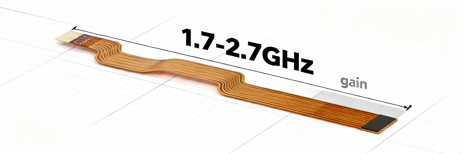
The 1.71–2.69 GHz region represents the primary resonance. In this window, S11 values remain consistently below -10dB (VSWR < 2:1), ensuring maximum power transfer. High directivity in the E-plane supports robust indoor penetration for IoT gateways.

Coexistence Note: Careful filtering is required when using the 2.4 GHz band simultaneously with Wi-Fi to prevent receiver desensitization.

Integration & Optimization Checklist

PCB Layout

Maintain a 10-20mm keepout zone from large metallic objects. Keep the ground plane consistent.

Matching Network

Use small series/shunt LC elements (1–10 nH / 0.5–5 pF) close to the feed to fine-tune S11.

Field Validation

Verify RSRP/RSSI and throughput against lab baselines in the final device enclosure.

Frequently Asked Questions

What is the expected VSWR for AANI-FB-0174-1? +
Engineers should expect a VSWR ≤ 2:1 within the primary 1.71–2.69 GHz frequency range. Outside this band, particularly in the sub-GHz region, VSWR will increase significantly, typically exceeding 3:1 without specialized matching.
How should I validate the antenna performance in a final product? +
Validation involves measuring S11/Return Loss on the fully assembled product. Field tests should include throughput analysis and RSRP/RSSI benchmarking in various environmental conditions to ensure link budget targets are met.
When is a matching network necessary? +
A matching network is recommended if the enclosure or nearby metal components cause a resonance shift. Adding series inductors or shunt capacitors allows designers to pull the resonance back into the desired frequency window, optimizing total efficiency.

Conclusion

The AANI-FB-0174-1 FPC antenna demonstrates superior efficiency and gain across mid-band cellular frequencies (1.71–2.69 GHz). While it offers usable performance for Wi-Fi coexistence, success depends heavily on ground plane integration and matching precision.

Mid-Band Optimization IoT Ready Lab-Validated