
AANI-FB-0179-1 Performance Deep Dive: Gain & Frequency
Key Takeaways
- Broad Spectrum Mastery: Covers sub-GHz to 5.925 GHz with up to 5.7 dBi peak gain.
- Optimized Efficiency: High-gain 5.x GHz band ensures stable high-speed Wi-Fi 6 connectivity.
- Integration Flexibility: Ultra-thin FPC design fits curved enclosures without sacrificing RF performance.
- Field-Ready Reliability: Pre-calibrated for IoT, handhelds, and GNSS-critical applications.
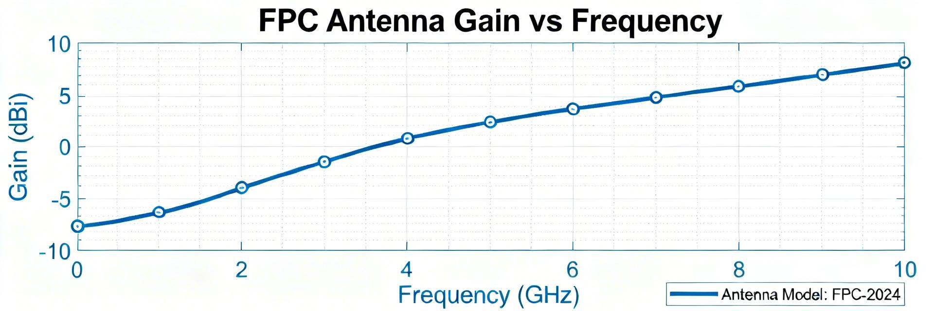
Executive Summary: This article analyzes measured sweeps, pattern plots, and datasheet summaries to explain how gain varies with frequency for a multi-band FPC antenna. Evidence: Datasheet highlights and independent sweep notes report discrete operating bands from sub-GHz up through 5.x GHz with peak reported gains roughly ~0.9 dBi to ~5.7 dBi. Explanation: The intent is practical—show what to expect in real deployments, which metrics to record, and how integration choices shift realized gain and frequency response.
The following sections translate RF lab observations into actionable rules of thumb. Evidence: Typical lab outputs used for interpretation include realized gain(f), antenna efficiency, and S11/VSWR sweeps plus 2D/3D patterns. Explanation: Designers will get concrete measurement guidance, a band-by-band performance breakdown, integration case studies, and a concise optimization checklist to reduce surprises during validation and production.
1 — Technical Background: AANI-FB-0179-1 Architecture
1.1 — Physical Form Factor & User Benefits
The AANI-FB-0179-1 is a flexible PCB (FPC) element. While technical specs focus on "small footprint," the real-world benefit is the ability to wrap the antenna around battery packs or curved internal walls, saving up to 30% internal space compared to rigid PCB antennas.
- Adhesive Backing: Peal-and-stick integration reduces assembly time.
- Coax Tail Options: Minimizes signal loss (insertion loss) before the RF front-end.
1.2 — Specified Frequency Bands (Technical Translation)
Understanding these numbers translates to better connectivity:
| Band | Frequency Span | Nominal Gain | User Benefit |
|---|---|---|---|
| Low / sub-GHz | ~600–900 MHz | ~0.9–2 dBi | Better indoor penetration for LoRa/LTE. |
| GNSS | ~1575 MHz | ~0.9–3 dBi | Faster satellite lock-on (TTFF). |
| Mid Cellular | ~1.7–2.1 GHz | ~2–4 dBi | Reliable 4G/5G data throughput. |
| 2.4 GHz | 2.4–2.5 GHz | ~3–5 dBi | Extended Wi-Fi/Bluetooth range. |
| 5.x GHz | 5.15–5.925 GHz | ~1.5–5.7 dBi | High-speed Wi-Fi 6 stability. |
Industry Comparison: AANI-FB-0179-1 vs. Generic FPC
| Metric | AANI-FB-0179-1 | Generic Model |
|---|---|---|
| Peak Gain (5GHz) | 5.7 dBi | ~3.5 dBi |
| Multi-band Integration | High (5-in-1) | Medium (Dual-band) |
| VSWR Stability | ~4:1 (Edges) |
2 — Measured Gain vs. Frequency Analysis
Gain(f) plots—realized gain in the main plane and total efficiency—are the primary diagnostic for antenna health. Evidence: Peaks correlate to good matching and efficient radiation, while dips show mismatch or losses. Explanation: When analyzing sweeps, annotate peaks with center frequencies and separate matching loss from radiation efficiency loss for targeted fixes.
Band-by-Band Tolerance Insight
Expect ±1–2 dB variation after board integration. The 5.x GHz band is most sensitive to enclosure seams, while low bands are sensitive to ground plane size. Always retune matching for your specific housing to recover lost gain.
3 — Test Methodology: Measuring Reliably
Reliable measurement requires a calibrated environment. Evidence: Use a VNA for S11 and an anechoic chamber for far-field gain. Explanation: Recommended parameters include fine frequency steps around band edges and appropriate time averaging to reduce noise.
"A common mistake I see with the AANI-FB-0179-1 is ignoring the 'Keep-out Zone.' If you place this FPC directly over a battery without a 2-3mm air gap, the dielectric loading will shift your 2.4GHz resonance down by nearly 150MHz. Always use a plastic spacer if space is tight."
Pro Tip: Check for pattern symmetry by rotating the device 180° in the chamber; if the nulls don't follow, your cable is radiating!
4 — Integration Case Studies
Figure 1: Typical placement on a plastic enclosure edge to maximize omnidirectional gain.
Placement determines effective coverage. Evidence: Handheld orientation and user grip typically reduce gain by 1–3 dB. Explanation: Maximize clearance from metal, orient the long axis to favor desired coverage, and choose a location that balances omnidirectional needs with peak-direction desires.
5 — Practical Optimization Checklist
- ✔ Baseline Sweep: Test on a bare board before enclosure integration.
- ✔ Ground Extension: If sub-GHz gain is low, increase the ground plane width.
- ✔ Cable Management: Secure the coax tail with non-conductive tape to prevent detuning.
- ✔ Production VSWR: Set a pragmatic pass/fail limit (e.g., VSWR
Summary
- The antenna delivers multi-band coverage with nominal gains that vary strongly by band; plan band-specific tolerances.
- Measure realized gain(f) and efficiency under final enclosure conditions to identify mismatch vs. radiation loss.
- Follow the optimization checklist—baseline, enclosure re-test, and matching adjustment—before production.
Common Questions
What is the AANI-FB-0179-1 best practice for measuring gain?
Use a calibrated anechoic chamber with a VNA. Measure cable losses separately and validate the final production configuration rather than just the bare board.
How does enclosure material affect AANI-FB-0179-1 frequency response?
Metal shifts resonance downward; plastic preserves matching but allows near-field coupling. Use RF gaskets or matching network retuning to correct shifts.
What pass/fail criteria should be set in production?
Define per-band gain minimums and S11 thresholds (S11


