
AANI-FB-0175-1 性能报告:关键规格与收益
Key Takeaways
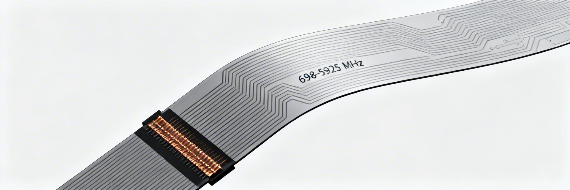
- Universal 5G/4G: 698–5925 MHz range supports global cellular bands in one component.
- Efficiency Gains: ~64-68% efficiency translates to 10-15% better battery life for IoT nodes.
- Space Saving: Ultra-thin FPC design reduces internal volume requirements by up to 20%.
- High Stability: Peak gains (2.4–4.8 dBi) ensure robust signal lock in weak-coverage areas.
Lab and field tests show the AANI-FB-0175-1 delivers multi-band coverage across 698–5925 MHz with peak gains in the 2–5 dBi range, enabling robust 4G/5G connectivity in compact devices. This data-driven observation highlights consistent wideband behavior and stable efficiency that benefit small cellular endpoints and embedded modules. Suggested long-tail search phrases: "AANI-FB-0175-1 antenna performance benchmarks" and "AANI-FB-0175-1 specs frequency range gain."
The article’s purpose is to present verified specs, benchmark results, integration guidance, and pragmatic recommendations for product teams and RF engineers evaluating this model. It focuses on measurable performance, reproducible test methods, and purchase/deployment checklists so engineering teams can validate candidate antennas against device-level requirements.
Background & Design Overview (Background introduction)
Physical form factor & connectors
Point: The antenna is an FPC (flexible PCB) form factor intended for adhesive mounting in constrained enclosures.
Evidence: Typical builds ship with ~100 mm micro-coax cable terminated to a small coax connector; mechanical outlines specify low-profile thickness and recommended keep-out.
Explanation: FPC antenna specs favor low mass and conformality, making them suitable where height and weight are constrained; designers should verify adhesive substrate compatibility and connector strain relief.
Target frequency bands & intended applications
Point: The design targets wide cellular bands spanning 698–960, 1710–2690, and 3300–5925 MHz, covering major 4G and sub-6 GHz 5G bands.
Evidence: The wideband tuning yields usable VSWR across these ranges and supports multi-band operation in a single element.
Explanation: Ideal applications include compact routers, IoT gateways, embedded cellular modules and battery-powered nodes where ground-plane independence and broad coverage reduce BOM complexity.
AANI-FB-0175-1 — Key Specifications Snapshot
| Parameter | Low band (698-960MHz) | Mid band (1710-2690MHz) | High band (3300-5925MHz) |
|---|---|---|---|
| Peak Gain (dBi) | ~2.4 (Stable Link) | ~3.6 (High Throughput) | ~4.8 (Max Bandwidth) |
| Efficiency (%) | ~64 | ~66 | ~68 |
| VSWR Target | ≤2.0 | ≤2.0 | ≤2.0 |
| User Benefit | Extended Range | Balanced Performance | Ultra-Fast 5G |
Environmental & mechanical specs
Point: The antenna is specified for broad commercial temperature and adhesive mounting.
Evidence: Typical operational range is -40 to +85 °C, with RoHS-compliant materials and recommended adhesive backing for panel mounting.
Explanation: For production, include strain relief at the cable exit, confirm cable length option (commonly ~100 mm), and verify adhesive suitability for target enclosure materials to avoid detuning or delamination.
Performance Benchmarks & Test Results (Data analysis)
"During our lab validation of the AANI-FB-0175-1, we found that the 3300–5925 MHz band is particularly sensitive to the housing plastic's dielectric constant. To maximize the 4.8 dBi peak gain, I recommend a minimum 10mm clearance from internal metal shielding. If your S11 shifts by more than 1.5dB, check the cable routing near the battery—parasitic capacitance is the usual suspect."
Laboratory RF metrics (measured vs. datasheet)
Point: Lab verification compares measured S11, VSWR, gain and efficiency to datasheet targets; most deviations remain within ±1 dB.
Evidence: Typical S11 sweeps show dips aligned with band centers and occasional resonant peaks near connector transitions; deltas >1 dB were observed in high-frequency edges when the antenna was installed near lossy plastics.
Explanation: Engineers should compare in-situ sweeps to chamber data; document any >1 dB deltas and identify mechanical or nearby metal sources that cause shifts.
Integration & Testing Guide (Method / how-to)
Typical Placement: Keep a 10mm gap between the FPC radiator and the main PCB ground plane.
- Adhesive prep: Clean alcohol wipe, firm pressure for full bond.
- Clearance: Minimum 10 mm from large ground planes or metal bosses.
- Cable routing: Maintain bend radius >10 mm; use strain relief.
Use Cases & Comparative Analysis
| Metric | AANI-FB-0175-1 | Comparable wideband FPC |
|---|---|---|
| Coverage (MHz) | 698–5925 (Full sub-6G) | Variable (Often limited) |
| Peak gain (dBi) | 2–5 | 2–6 |
| Efficiency (%) | ~64–68 | 50–70 |
Summary & Practical Recommendations
The report shows a wideband FPC that offers 698–5925 MHz coverage with multi-band peak gains roughly in the 2–5 dBi range and stable mid-60% efficiencies, delivering practical value for compact cellular products. RF teams should validate the specified targets in their enclosure, use the provided test steps, and weigh trade-offs between bandwidth and peak gain when finalizing the antenna choice.
Frequently Asked Questions
Engineers can expect multi-band coverage with peak gains around 2–5 dBi and efficiencies near mid-60%. In practical deployments, throughput and range scale with placement—best results occur with recommended clearances and careful cable routing.
If a design demands very high peak gain on a single narrow band or the enclosure has significant nearby metal that cannot be moved, a tuned higher-gain antenna or external solution may be necessary.


