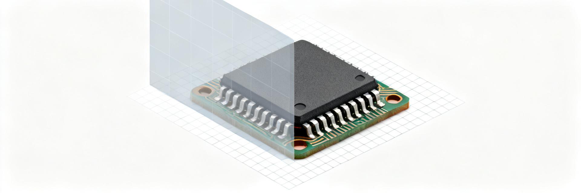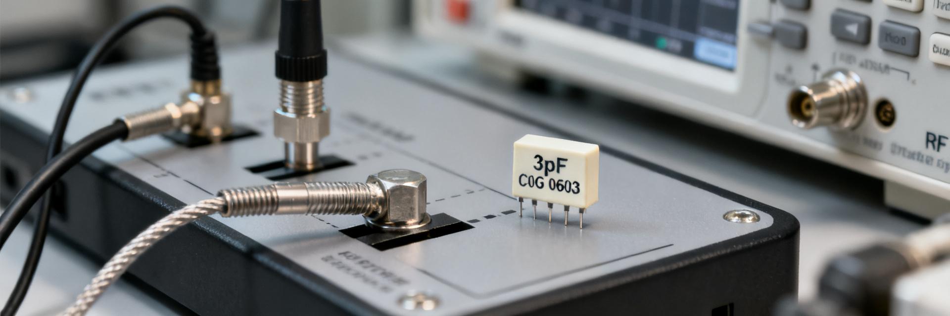
In many BOMs and component libraries, the 470pF X7R 0603 50V capacitor appears among commonly used MLCC values for decoupling and filtering because its small footprint and moderate voltage rating fit mixed-signal and power-rail designs. This article explains what the part name implies, highlights the key capacitor specs engineers must check, and offers practical PCB selection and assembly guidance. The manufacturer SKU GMT10X7R471K50NT4 is a typical industry example for this class of part.
Background: What "470pF X7R 0603 50V" means
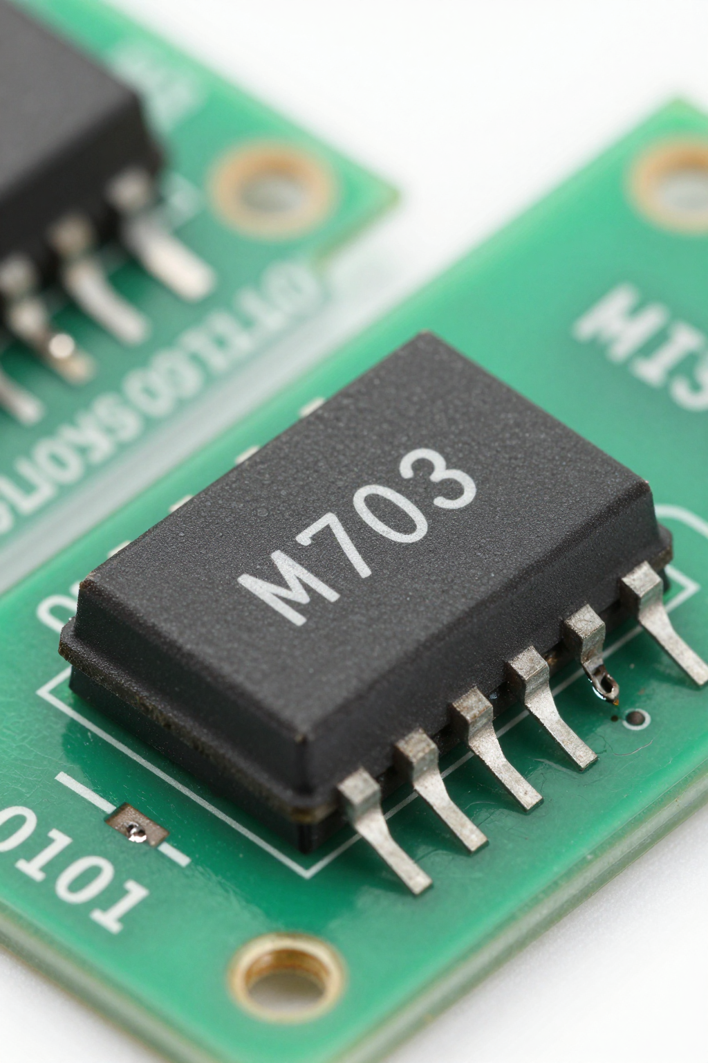
Physical footprint: 0603 (what to state)
The designation 0603 indicates an imperial footprint of 0.06" × 0.03", approximately 1.6 mm × 0.8 mm, with typical maximum thickness around 0.8–0.9 mm depending on manufacturer. A 470pF X7R 0603 50V capacitor in this package balances board area and capacitance for many designs. Handling and pick-and-place are straightforward for 0603 parts, but designers should confirm tape-and-reel orientation and recommended land pattern from the datasheet before layout.
Dielectric & temperature behavior: X7R explained
X7R is a Class II ceramic dielectric specified for −55°C to +125°C with typical capacitance variation limited to ±15% over that range. Compared with C0G/NP0, X7R offers much higher volumetric capacitance but less stability versus temperature and DC bias. Practically, X7R suits general decoupling and bypass where space and bulk capacitance matter; it is not recommended for precision timing or frequency-determining networks where minimal tempco and drift are required.
Data: Electrical specs & performance (use "capacitor specs" here)
| Parameter | Value / Specification | Notes |
|---|---|---|
| Nominal Capacitance | 470 pF | Code: 471 |
| Tolerance | ±10% (K) | Also available in ±5% (J) or ±2% (G) |
| Rated Voltage | 50 V DC | Continuous operation limit |
| Dielectric Material | X7R | Class II, Temp Range -55°C to +125°C |
| Package Size | 0603 (Imperial) | 1608 Metric (1.6mm x 0.8mm) |
| Termination Finish | Silver/Palladium/Nickel/Tin | Lead-free compliant |
Key specs to list and interpret
Essential capacitor specs include nominal capacitance 470 pF, typical tolerance ±10% (some vendors offer ±5% or ±1% variants), and rated voltage 50 V DC — rated for continuous operation at that voltage. Other important specs are insulation resistance/leakage, termination finish, and recommended operating temperature. The phrase capacitor specs should be used to organize checklist items when comparing datasheets during part selection.
Performance effects engineers must check
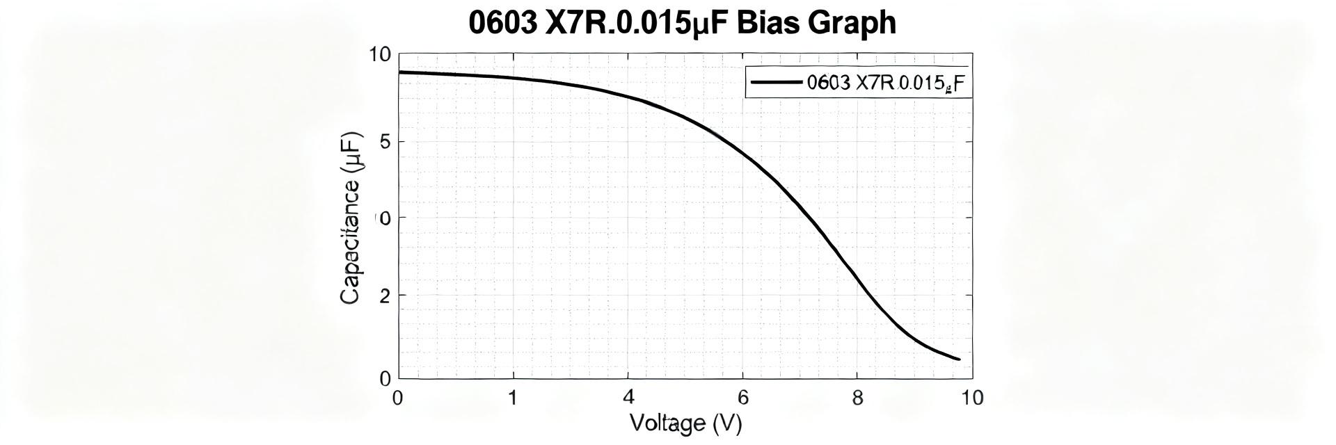
DC-bias reduces effective capacitance in X7R parts; a 470 pF X7R may lose 10–60% of capacitance under applied DC depending on construction, so check the manufacturer DC-bias curve. Frequency response is characterized by reactance Xc = 1/(2πfC): for 470 pF, Xc ≈ 339 Ω at 1 MHz and ≈ 3.39 kΩ at 100 kHz. ESR and ESL are low for MLCCs but vary by size and vendor; review impedance vs frequency plots on datasheets for decoupling use.
Selection & PCB design guidelines
How to choose the right 470pF X7R 0603 50V part
Choose a 50V rating when board rails approach high voltages or when derating for DC-bias margin is needed; higher voltage parts often show improved DC-bias retention. If stability or minimal bias loss is critical, specify NP0/C0G or a larger package rather than X7R. Also consider tolerance and availability—±10% is common and economical, but ±5% or ±1% may be necessary for tighter filter or timing requirements.
Footprint, pad design and assembly notes
Recommended land patterns for 0603 typically use pad lengths around 0.9–1.0 mm and pad widths near 0.6 mm; follow IPC guidance and the part's datasheet. Solder paste apertures of roughly 60–70% of pad area help control fillet and reduce tombstoning risk. During assembly, avoid large adjacent thermal masses that can cause uneven heating. Inspection and X‑ray are useful for verifying solder fillets and detecting internal cracks on small MLCCs.
Comparison & trade-offs (case study mindset)
470pF X7R vs NP0/C0G (dielectric trade-offs)
NP0/C0G provides near-zero temperature coefficient and negligible DC-bias effects, making it ideal for timing and precision filters, but its volumetric capacitance is lower than X7R. For the same 470 pF at 50 V, NP0 may require a larger package or multiple parts in parallel, increasing board area and cost. X7R is preferable when space and cost dominate and moderate stability is acceptable.
0603 vs other case sizes (performance vs manufacturability)
0603 strikes a balance between capacitance density and assembly ease. Smaller sizes (0402, 0201) reduce solderable area and available capacitance at 50 V, and they increase handling difficulty and risk of workmanship defects. Larger sizes (0805, 1206) offer higher maximum capacitance, often better DC-bias retention and slightly lower ESR/ESL, but consume more board area and may be unnecessary for dense layouts.
Procurement, testing & reliability checks
What to verify on the datasheet before buying
Before procurement confirm exact dimensions and thickness, termination finish, rated voltage and dielectric (X7R), tolerance, operating temperature range, DC-bias curve, impedance vs frequency plots, and recommended land pattern. Verify packaging (tape & reel), minimum order quantity and lead time, and that RoHS/lead-free finishes are specified. For traceability, capture the vendor part number and internal SKU such as GMT10X7R471K50NT4 on purchase records.
Practical test checklist for incoming parts and prototype validation
Incoming inspection should include LCR meter checks at relevant frequencies and biased voltages to validate DC-bias behavior, solderability testing with a representative reflow profile, and visual/X-ray inspection for internal defects. Use statistically based sampling for acceptance testing, and consider thermal cycling and humidity testing for reliability assurance. Account for board flex and mounting stresses; MLCCs can crack under mechanical strain.
Summary
- A 470pF X7R 0603 50V capacitor denotes a 470 pF multilayer ceramic (X7R) in a 0603 package rated for 50 V; check capacitor specs such as tolerance, DC-bias curve, and impedance before selection.
- Expect significant DC-bias capacitance reduction with X7R—verify manufacturer curves and consider higher voltage parts or alternate dielectrics for critical circuits.
- Use recommended 0603 land patterns, control paste apertures to avoid tombstoning, and validate parts with LCR bias testing and reflow inspection for reliable assembly.
Frequently Asked Questions
How does a 470pF X7R 0603 50V capacitor behave under DC bias?
Under DC bias an X7R MLCC can lose a significant portion of its nominal capacitance; typical reductions for a 470 pF 0603 part range from about 10% up to 60% depending on construction and applied voltage. Engineers should measure or consult the manufacturer's DC-bias curve at the intended operating voltage to determine effective capacitance for the application.
When should a designer choose a 50V 470pF X7R over NP0/C0G?
Choose 50V X7R when board space and bulk decoupling are priorities and circuit tolerance for temperature and bias-induced drift is acceptable. If minimal tempco and near-zero DC-bias behavior are required for timing or precision filtering, NP0/C0G—or a larger package to achieve required capacitance at 50V—will be the better choice.
What basic tests should be run on 470pF X7R 0603 50V parts in prototype builds?
Prototype validation should include LCR measurements at the circuit's operating frequency and under bias voltages to quantify DC-bias effects, a controlled reflow soldering trial to check solderability and cracking, and sample environmental stress tests (thermal cycling, humidity). Visual and X‑ray inspections help catch assembly and internal defect issues early.
What are the physical dimensions of a 0603 capacitor?
The designation 0603 indicates an imperial footprint of 0.06" × 0.03", approximately 1.6 mm × 0.8 mm, with typical maximum thickness around 0.8–0.9 mm depending on the manufacturer.