The 0603 C0G 390pF 50V capacitor is a common choice where stability and low loss matter: designers building precision timing, filtering and RF front-ends frequently specify MLCCs with near-zero temperature coefficient and minimal dielectric loss. This article gives a hands-on walkthrough of the part’s datasheet, the key electrical and mechanical specs to check, real-world performance expectations, application examples, sourcing guidance and practical assembly/test tips. For verification, use a sample search term like "GMT10CG391J50NT4 datasheet" to confirm vendor entries and test conditions.
1 — Background: What "0603 C0G 390pF 50V" means
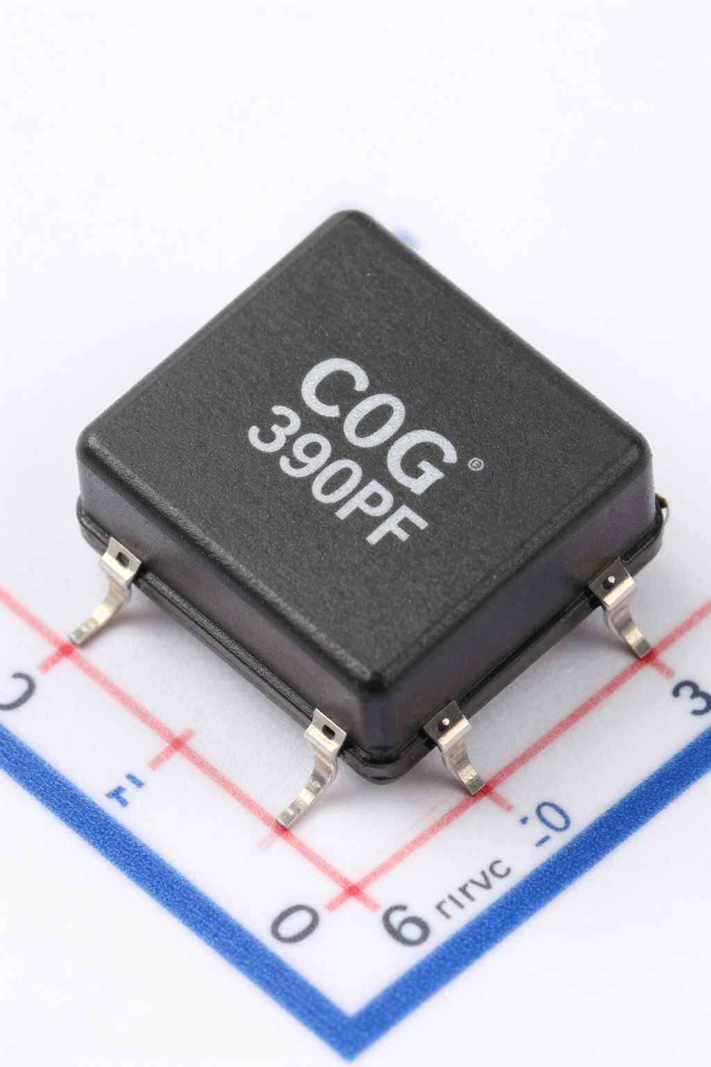
At a glance this label encodes four essentials: 0603 (imperial) package, C0G dielectric, 390 pF nominal capacitance and 50 VDC rating. In compact PCBs the 0603 footprint balances available board space with acceptable parasitics for many RF and timing uses. The C0G (NP0) dielectric guarantees near-zero temperature coefficient (~0 ±30 ppm/°C) and very low dissipation factor compared with X7R/X5R. That stability is why designers choose a 390 pF C0G in oscillator networks, ADC front-ends and precise filter corners where capacitance shift would degrade performance.
1.1 — Form factor & dielectric explained
0603 (1608 metric) yields small pad area and lower board real estate but slightly higher lead and dielectric parasitics versus larger packages. C0G/NP0 offers the flattest capacitance vs temperature and frequency, minimal aging and low DF, making it preferred when ppm-level stability and low phase shift matter. By contrast X7R/X5R provide higher volumetric capacitance but exhibit larger DC bias and temperature-dependent shifts, so they suit bulk decoupling, not precision timing.
1.2 — Typical electrical envelope
Nominally 390 pF with common tolerance codes ±1% (J) or ±5% (K). Rated voltage 50 VDC indicates the maximum continuous DC stress; typical leakage and IR specs depend on dielectric and process. Use "0603 C0G 390pF 50V" in parts searches to confirm the footprint/voltage/capacitance match the design intent and to verify tolerance and DF values in the datasheet.
2 — Datasheet walkthrough: key fields to read
Datasheets list many entries; prioritize electrical test conditions, mechanical dimensions and reliability data. Understanding the measurement conditions (frequency, test voltage, temperature) is essential to interpret DF, IR and SRF numbers that affect circuit behavior. When evaluating a vendor sheet, confirm the test frequency used for DF and that insulation resistance is measured at a stated voltage and time.
| Parameter | Typical Value / Spec | Importance |
|---|---|---|
| Capacitance | 390 pF ±1% (J) | Defines timing constants and filter poles. |
| Tolerance Code | J (±1%) or K (±5%) | Critical for precision analog circuits. |
| Rated Voltage | 50 VDC | Maximum continuous DC stress allowed. |
| Temp Coefficient | 0 ±30 ppm/°C (C0G) | Ensures stability across temperature ranges. |
| Dissipation Factor | < 0.1% @ 1 MHz | Low loss is vital for Q-factor in RF circuits. |
| Self-Resonant Freq | ~150–300 MHz | Upper limit for effective capacitive operation. |
2.1 — Electrical specifications to prioritize
Focus on nominal capacitance, tolerance, rated voltage, temperature coefficient (ppm/°C), dissipation factor (DF or tan δ) at a given frequency, insulation resistance (or leakage) and self‑resonant frequency (SRF). Check measurement frequency (e.g., 1 MHz or a specified RF range) and temperature at which DF/IR were recorded. A datasheet like the example "GMT10CG391J50NT4 datasheet" should clearly tabulate these entries and test conditions for reliable comparisons.
2.2 — Mechanical & reliability data
Verify package dimensions, electrode/termination finish, recommended land pattern and solder paste stencil guidance. Look for moisture sensitivity level (MSL), mechanical shock/vibration curves and recommended reflow profile limits. These fields reveal assembly risk (tombstoning, cracking) and help you request additional supplier documents—qualification test reports or lot traceability—when procuring production quantities.
3 — Electrical performance & real-world behavior
C0G capacitors are predictable: capacitance is stable across temperature and frequency ranges meaningful to most precision analog and many RF applications. Still, designers must consider SRF and small but finite voltage dependence for accurate high-frequency or high‑Q circuit behavior. Use bench measurements to validate datasheet numbers under real load and mounting conditions.
3.1 — Frequency and temperature behavior
C0G maintains capacitance within a few tens of ppm/°C and shows minimal dispersion with frequency until approaching SRF. For a 390 pF in 0603, expect SRF in the low hundreds of MHz depending on package parasitics and board layout—sufficient for many RF bypass and matching tasks but verify with an impedance sweep in-circuit when designing resonant or high-Q networks.
3.2 — Voltage coefficient, aging and derating
DC bias effect for C0G is small but measurable at high fields; derate conservatively if precision under DC is required—e.g., allow a few percent headroom from rated voltage. Aging is negligible for C0G compared to ferroelectric dielectrics; nevertheless, verify stability after thermal cycling. Rule of thumb: limit continuous DC stress to ≤60–80% of rated voltage for tight tolerance applications.
4 — Typical applications & circuit examples
390 pF at 50 V with C0G is a go-to value where stability and low loss matter: timing RC networks, oscillator capacitors, RF matching or bypass where a predictable corner is required, and ADC front-end filtering. The 50 V rating gives headroom in mixed-signal systems where supply transients or bias networks can impose higher voltages.
4.1 — Common use cases
Common placements include crystal or MEMS oscillator loading, RF matching stubs, ADC input anti-alias filters and compensation networks in precision amplifiers. Designers choose 390 pF when the desired pole or resonance frequency and layout constraints align; 50 V rating protects against bias-induced capacitance shifts in circuits with moderate DC offsets.
4.2 — Short circuit examples (how to place & combine)
In an RC timing network at tens of kHz, a single 390 pF C0G yields stable timing against temperature swings. To combine functions, parallel a C0G 390 pF with a higher‑value X7R for bulk charge buffering—C0G preserves timing stability while X7R provides capacitance density and lower ESR for low-frequency decoupling.
5 — Selection, cross-referencing & sourcing checklist
Part numbers encode size, dielectric, capacitance code, tolerance and voltage. Confirm each field: a typical code will include package (0603), dielectric (CG or NP0), capacitance code (391 → 390 pF), tolerance letter (J/K) and voltage (50). Use targeted searches like "GMT10CG391J50NT4 datasheet" to cross-check the annotated fields and measurement conditions in supplier documentation before ordering.
5.1 — How to match equivalents and read part numbers
When cross-referencing, ensure size and dielectric match first, then tolerance and voltage. Equivalent parts must show comparable DF, IR and SRF data. Confirm termination material and MSL rating to avoid surprises in assembly; identical capacitance with different electrode finishes can affect solderability and reliability.
5.2 — Procurement & quality checklist
Require full datasheet, date codes, lot traceability and certificate of conformity. Check MOQ, reel vs. cut-tape options, MSL level and storage recommendations. For critical production, request sample lots, perform incoming inspection and simple electrical validation (capacitance, DF, IR) to catch counterfeit or out-of-spec lots early.
6 — PCB layout, assembly & testing best practices
Layout and process choices directly affect MLCC performance and reliability. Optimize land patterns to balance fillet formation and reduce tombstoning risk; give modest solder fillet lands and follow vendor recommended pad sizes. Use stress-relief routing for components near board edges or on flex sections to prevent mechanical cracking.
6.1 — PCB footprint and soldering recommendations
Use the manufacturer’s recommended land pattern for 0603 to control fillet geometry and wetting. Follow a controlled reflow profile with max peak temperatures specified on the datasheet to avoid thermal shock. For small MLCCs, keep pick-and-place and reflow parameters within vendor limits to minimize tombstoning and micro-cracking.
6.2 — Test & validation steps
Validate with capacitance vs frequency sweeps, DF/tanδ measurements at the intended operating frequency, and IR/leakage tests at rated/biased voltages. Perform visual inspection for solder joints and hairline cracks. If failures appear, isolate soldering thermal stress or board flex as potential root causes and add layout changes or relief cuts as mitigations.
Summary
The 0603 C0G 390pF 50V capacitor offers excellent stability, low loss and predictable behavior, making it well suited for precision timing, RF matching and ADC front-ends. Verify critical datasheet fields—capacitance/tolerance, DF, IR, SRF, mechanical dimensions and MSL—and validate vendor test conditions. In layout and assembly, follow recommended land patterns, controlled reflow and incoming electrical checks. Before procurement, run the sourcing checklist and request datasheet documentation (search the example term "GMT10CG391J50NT4 datasheet") to confirm equivalence and quality.
- Stability: C0G gives near-zero temperature coefficient and minimal aging, ideal when capacitance must remain constant in timing or RF circuits.
- Datasheet priorities: check DF/tanδ at stated frequency, IR/leakage at specified conditions and SRF for high‑frequency designs.
- Sourcing checklist: confirm package, dielectric, tolerance, voltage, MSL and lot traceability; perform incoming capacitance and DF spot checks.
Frequently Asked Questions
What does C0G mean in capacitor specifications?
C0G (also known as NP0) indicates a Class I ceramic dielectric with a near-zero temperature coefficient (~0 ±30 ppm/°C) and very low dissipation factor, making it ideal for precision timing and RF applications.
Why is Self-Resonant Frequency (SRF) important for 0603 capacitors?
SRF determines the frequency at which the capacitor behaves as an inductor due to parasitic ESL. For high-frequency designs, operating below the SRF ensures the component remains capacitive, preserving circuit integrity.
How should I derate voltage for C0G capacitors?
Although C0G has minimal DC bias effect, it is recommended to limit continuous DC stress to 60–80% of the rated voltage (e.g., 30-40V for a 50V part) in tight tolerance applications to ensure long-term reliability and stability.
What are common pitfalls when ordering 0603 C0G parts?
Ensure the termination material matches your soldering process and check Moisture Sensitivity Level (MSL). Verify that the specific part number (e.g., GMT10CG391J50NT4) corresponds to the exact tolerance and voltage rating required by your design.