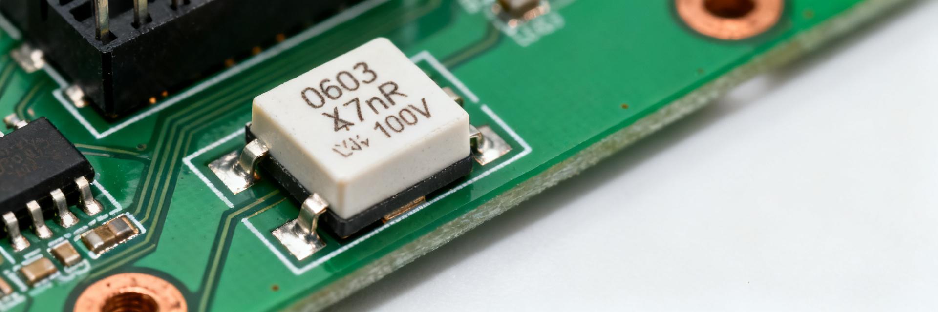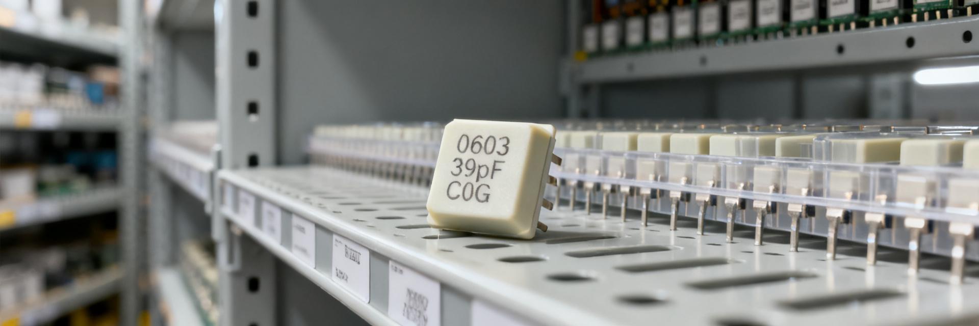
Demand for higher capacitance in smaller footprints is rising as portable and IoT product designs push decoupling closer to power rails; designers increasingly specify MLCC in 0603 packages to reclaim PCB area while preserving transient performance. Evidence from recent supply analyses shows shrinking board area and higher switching currents drive wider use of 1.5uF parts, so this guide focuses on measured limits and practical trade-offs.
The purpose of this guide is to summarize real-world performance limits, validation tests, and pragmatic sourcing strategies for 1.5uF 0603 X5R 16V capacitors. It aims to help engineers translate datasheet numbers into expected in-circuit capacitance, assembly constraints, and procurement actions that reduce lifecycle risk.
Why designers choose 1.5uF 0603 X5R 16V
Integrating high capacitance directly into sub-1mm design profiles requires components that maximize volumetric density. Below is the simplified equivalent model representing the inner layers and parasitic attributes of the MLCC in an 0603 layout footprint.
Electrical characteristics to cover
Point: 1.5uF nominal with typical X5R characteristics offers high volumetric density compared with C0G/NPO. Evidence: typical tolerance is ±10% or ±20%, rated voltage 16V, and room-temperature ESR/ESL for 0603 X5R parts is low but higher than larger packages. Explanation: designers accept higher drift and DC-bias loss in exchange for space savings and lower cost per µF when specifying 1.5uF X5R 0603 components.
Mechanical & manufacturing considerations
Point: The 0603 footprint changes assembly risk profile compared to larger packages. Evidence: placement accuracy, tombstoning susceptibility, and reflow thermal mass are all constrained in 0603; recommended land patterns and paste coverage matter. Explanation: tight pick-and-place tolerances and optimized paste stencil apertures reduce misplacement and improve solderability, directly affecting yield for dense decoupling arrays.
Performance trade-offs: DC-bias, temperature, and effective capacitance
DC-bias vs. usable capacitance
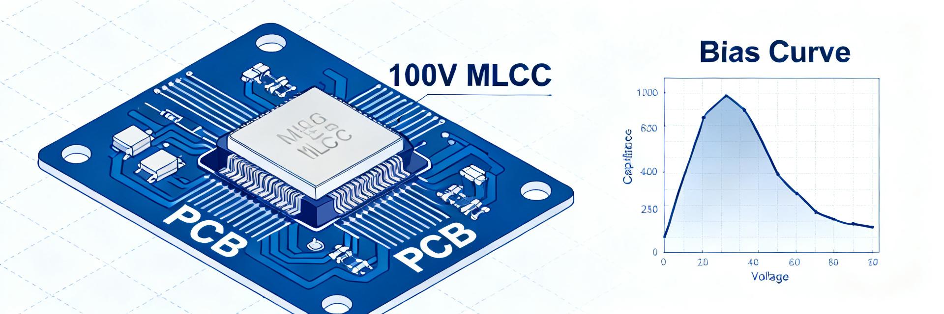
Point: X5R ceramics exhibit significant DC-bias capacitance reduction as voltage increases; usable capacitance at operating voltage can be substantially below nominal. Evidence: conservative lab curves for 1.5uF X5R 16V parts commonly show 30–60% remaining capacitance at 8–12V depending on construction. Explanation: because effective decoupling depends on in-circuit capacitance, engineers must measure capacitance vs. voltage for target operating points rather than rely on nominal values.
Temperature and aging impacts
Point: Temperature coefficients and aging reduce effective capacitance over time and with heat exposure. Evidence: X5R stability is specified to ±15% over the rated temperature range (typically −55°C to +85°C), and aging can cause a logarithmic capacitance decline after initial bake-in. Explanation: BOM entries should include temperature derating and aging assumptions so ripple handling and decoupling budgets remain valid across life and operating temperature.
| Performance Metric | Nominal Datasheet Spec | Effective Real-World Performance |
|---|---|---|
| Capacitance (C) | 1.5 µF ±10% or ±20% | 0.45 µF to 1.05 µF under 16V bias |
| Temperature Stability | X5R (±15% over -55°C to +85°C) | Subject to additional logarithmic aging (~1.5% per decade hr) |
| ESR / ESL (0603) | Low milliohm range | Higher self-resonance, optimized for high frequencies |
Selecting parts and mitigating supply risk
Part selection criteria & cross-reference checklist
Point: A concise BOM must capture critical fields to evaluate fit and risk. Evidence: required fields include capacitance (1.5uF ± tolerance), dielectric (X5R), rated voltage 16V, package 0603, termination finish, DC-bias curve, and moisture sensitivity level. Explanation: include DC-bias curves and frequency impedance plots in the spec sheet, list acceptable relaxations (e.g., 25V 0603 with similar DC-bias may be acceptable), and track cross-reference part numbers such as GMT10X5R155K16NT4 for quick substitution during quoting.
Procurement strategies to reduce lifecycle risk
Point: Multi-sourcing and safety stock are effective mitigations for MLCC volatility. Evidence: splitting orders across authorized suppliers, maintaining a short safety stock, and qualifying a 0805 or 25V alternative reduces single-source exposure. Explanation: during RFQs request DC-bias and reflow data, keep alternate part numbers in the BOM, and plan staggered orders to smooth lead-time spikes while documenting qualifying data for each supplier; note GMT10X5R155K16NT4 as a qualified alternate where applicable.
Design verification and quality checks
Electrical test procedures
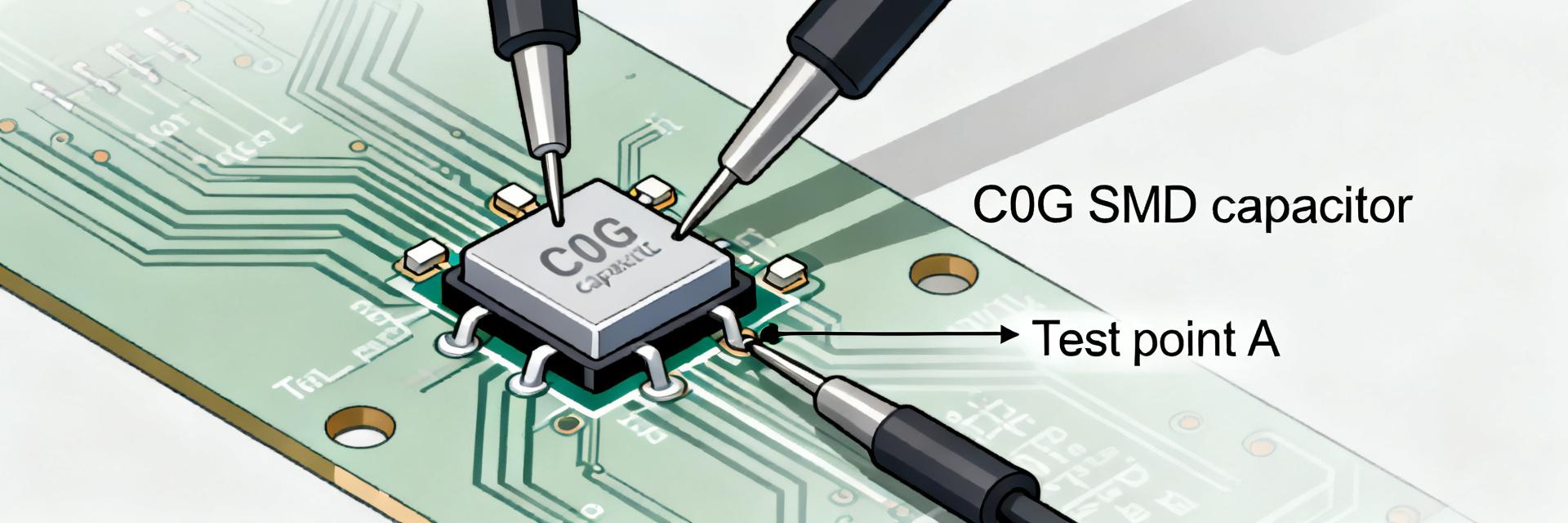
Point: Targeted electrical tests validate usable capacitance and thermal behavior under real conditions. Evidence: routine procedures should include capacitance vs. voltage sweeps, ESR/impedance across the frequency band of interest, and ripple-current heating tests at expected operating temperature. Explanation: use an LCR meter for V-dependent curves, a network analyzer for impedance, and a thermal chamber plus calibrated thermocouples for ripple-induced heating; document pass/fail criteria such as ≤20% capacitance shift under nominal bias.
Environmental & assembly qualification
Point: Assembly and reliability testing reduce field failures tied to soldering or environment. Evidence: perform reflow solderability checks, thermal cycling, humidity soak with reflow, mechanical shock, and vibration tests on representative builds. Explanation: specify minimum sample sizes (e.g., 30 units for initial qualification), acceptance criteria (e.g., ≤5% capacitance change, no visual solder defects), and request extended qualification data from suppliers when products carry long lifecycles.
When to use 1.5uF 0603 X5R 16V and backup options
Design rules of thumb and layout tips
Point: Placement and parallelization choices directly affect decoupling effectiveness. Evidence: keep 0603 decoupling within 1–3 mm of the IC power pins, use vias to reduce loop inductance, and place multiple caps to spread broadband decoupling. Explanation: for high-current rails parallel several values (e.g., 1.5uF X5R plus 0.1uF C0G) to cover low- and high-frequency noise; apply moderate derating by planning for reduced in-circuit capacitance from DC-bias and temperature.
Viable substitutes and when to pick them
Point: Alternatives trade space for electrical robustness. Evidence: 0805 packages typically retain a larger fraction of nominal capacitance under bias and show lower ESR/ESL; higher-voltage X5R parts or combining multiple smaller parts reduce bias loss. Explanation: choose a larger package when DC-bias performance or ripple current capacity is critical, or parallel two smaller caps to meet both bias and frequency response goals while retaining board-area flexibility.
Summary
In recap, 1.5uF 0603 X5R 16V MLCCs deliver high volumetric density for decoupling but require explicit verification of DC-bias, temperature, and assembly behavior. Engineers should validate effective capacitance in-circuit, specify full BOM fields including DC-bias curves, qualify multiple suppliers, and keep alternates ready to manage lifecycle risk.
- Validate DC-bias: measure capacitance vs. voltage for the operating point and specify DC-bias curves on the BOM to ensure effective decoupling in the end system.
- Specify full BOM fields: include capacitance, tolerance, dielectric, rated voltage, package, DC-bias, termination finish, and temperature ratings to avoid misinterpretation during procurement.
- Mitigate supply risk: multi-source, keep safety stock, and qualify alternates (larger package or higher voltage) while documenting electrical trade-offs for each option.
FAQ
How does DC-bias affect MLCC usable capacitance for 1.5uF parts?
DC-bias in X5R ceramics reduces effective capacitance as applied DC voltage rises; for 1.5uF 16V 0603 parts measured in-circuit capacitance can drop to 30–70% of nominal depending on construction. Engineers must capture capacitance vs. voltage curves for design margins and avoid assuming nominal values under bias.
Are 1.5uF 0603 X5R 16V capacitors reliable after reflow and environmental stress?
With correct land patterns and paste coverage, 0603 X5R parts survive standard reflow profiles, but qualification should include solderability, thermal cycling, and humidity + reflow tests. Acceptance criteria typically allow only small capacitance shifts (e.g., ≤5–10%) and no solder defects for production acceptance.
What procurement steps reduce the risk of MLCC shortages for production?
Adopt multi-sourcing, maintain short safety stock, qualify close alternates, and require DC-bias and reflow data during quoting. Track alternate part numbers and performance data in the BOM to enable rapid substitution; documenting these steps ahead of demand spikes lowers downtime risk.
Why choose X5R dielectric over C0G/NP0 for 1.5uF at 0603 package size?
X5R offers the necessary high volumetric efficiency to achieve 1.5uF in an 0603 footprint. C0G/NP0 dielectrics have much lower permittivity, meaning a 1.5uF C0G capacitor would require a massively larger package size, making it unusable for space-constrained PCB layouts.