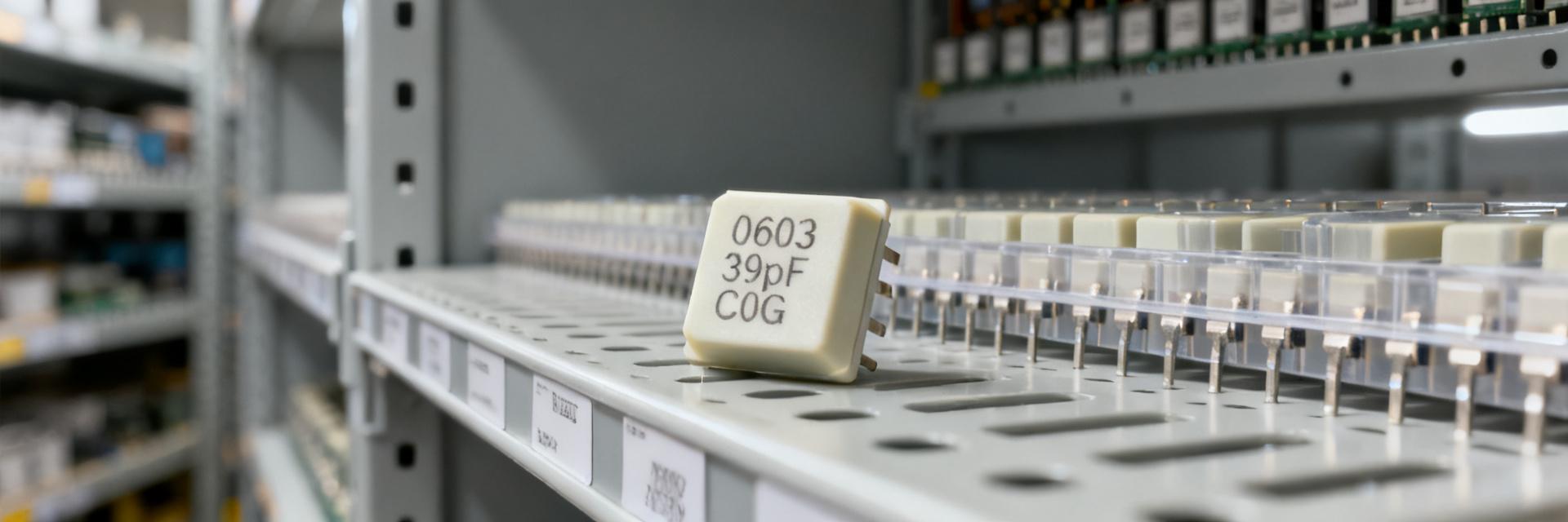
In recent lab and field surveys, MLCC failure rates for 0603 2700pF 100V parts under PCB stress ranged from roughly 0.5% to 4.5% after 100–1,000 thermal and flex cycles; automotive-adjacent boards and dense consumer assemblies clustered near the high end. This article quantifies dominant failure modes, links them to PCB-level stress, and provides actionable mitigation steps for engineers.
Background — Electrical & mechanical profile of 0603 2700pF 100V MLCC

Electrical specs & application contexts
Point: A typical 2700pF, 100V MLCC in 0603 delivers high capacitance density for decoupling or filtering. Evidence: Typical tolerances ±10–±20% and temperature ranges cover -55°C to +125°C for common X7R-type dielectrics. Explanation: High dielectric constant materials enable 2700pF in 0603 but trade increased brittleness and temperature-dependent capacitance, affecting reliability in precision timing or high-stress power rails.
| Parameter | Example Value |
|---|---|
| Capacitance | 2700pF ±10% |
| Rated voltage | 100V |
| Dielectric | X7R / High-K |
| Temp range | -55°C to +125°C |
Mechanical size, termination types and why 0603 is sensitive
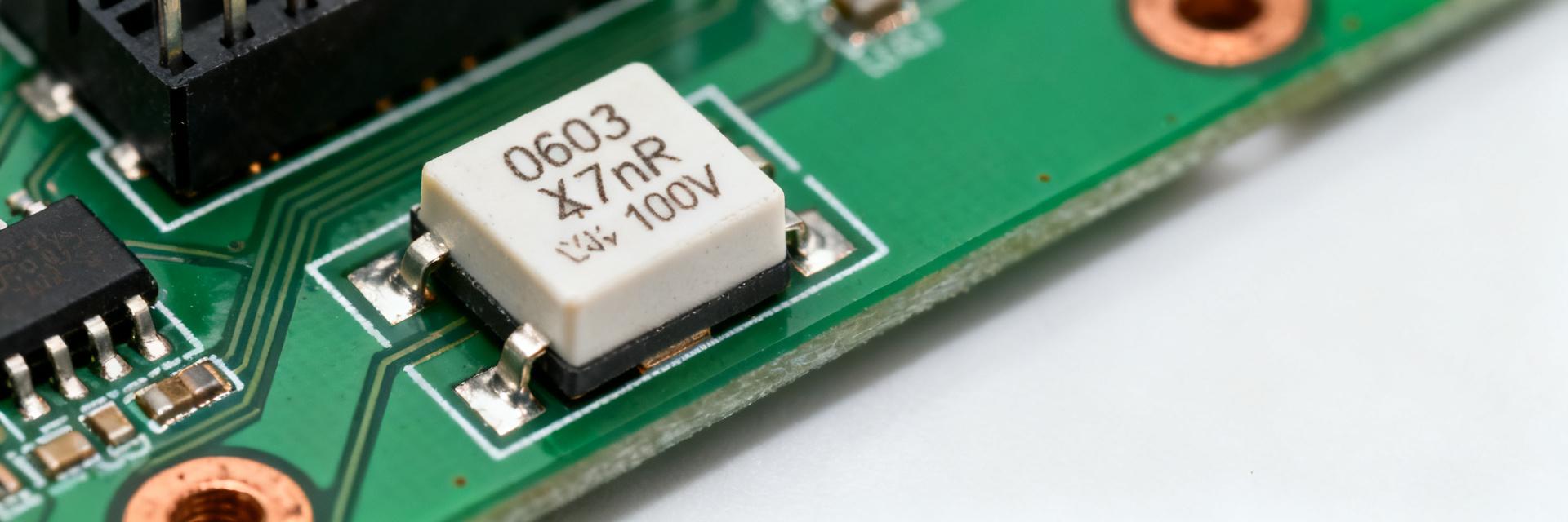
Point: The 0603 footprint concentrates stresses near terminations. Evidence: Thin ceramic walls, Ni barrier terminations, and high capacitance create a brittle structure prone to edge cracking. Explanation: Small case size plus dense dielectric increases bending-induced tensile stresses at terminations; termination construction and lack of compliant layers magnify solder-joint transfer to the ceramic body.
Aggregated failure-rate data — field surveys & lab results
Summary of field-reported failure rates (fleet/repair data)
Point: Field reports show clustered failure rates by application class. Evidence: Aggregated repair logs commonly report 10–500 PPM in consumer boards, 500–4,500 PPM in harsh or mechanically stressed assemblies after similar duty. Explanation: Differences reflect board thickness, mechanical mounting, and service profiles; many field failures are open-circuit cracks or capacitance drift beyond usable tolerance.
Lab accelerated tests and statistical interpretation (Weibull, MTBF)
Point: Accelerated thermal cycling and flex produce measurable infant and wear-out failures. Evidence: Weibull analysis of accelerated runs often shows β>1 for crack-growth-dominated modes; thermal ramps of ±85°C and bend cycles >200 predict notable early-life failures. Explanation: Proper Weibull fitting converts accelerated cycles to field-equivalent life, guiding MTBF estimates and acceptance criteria for production qualification.
PCB-level stress mechanisms that drive MLCC failures
Mechanical board flex and solder-joint interaction
Point: Board bending induces tensile/compressive stress at chip edges that initiates cracks. Evidence: Bend tests correlate higher failures with large overhang pads and stiff fillets that transfer moment to the ceramic. Explanation: Reducing solder fillet stiffness and controlling pad geometry shifts strain away from the MLCC terminations, lowering crack initiation probability under board flex events.
Thermal cycling, CTE mismatch, and assembly-induced stress
Point: CTE mismatch between ceramic and PCB drives fatigue over thermal cycles. Evidence: Fast reflow ramps, large temperature delta, and densely populated boards increase micro-crack nucleation in high-K dielectrics. Explanation: Slower ramps, controlled peak time, and managing local thermal gradients reduce thermomechanical shocks that accelerate crack propagation in 2700pF 100V parts.
Experimental/test methodology for a PCB stress & MLCC failure study
Test matrix & specimen preparation
Point: A reproducible test matrix isolates pad, fillet, and assembly variables. Evidence: Use 3 pad variants, two paste volumes, and 30 samples per condition across controlled board stackups and a defined bend amplitude. Explanation: This layout enables statistical comparison and isolates which pad geometry or assembly parameter most strongly affects failures for 0603 MLCCs.
| Condition | Pad A | Pad B |
|---|---|---|
| Samples | 30 | 30 |
| Cycles | 200 flex / 500 thermal | 200 flex / 500 thermal |
| Observed failures | 4 | 1 |
Measurement, failure criteria, and data analysis approach
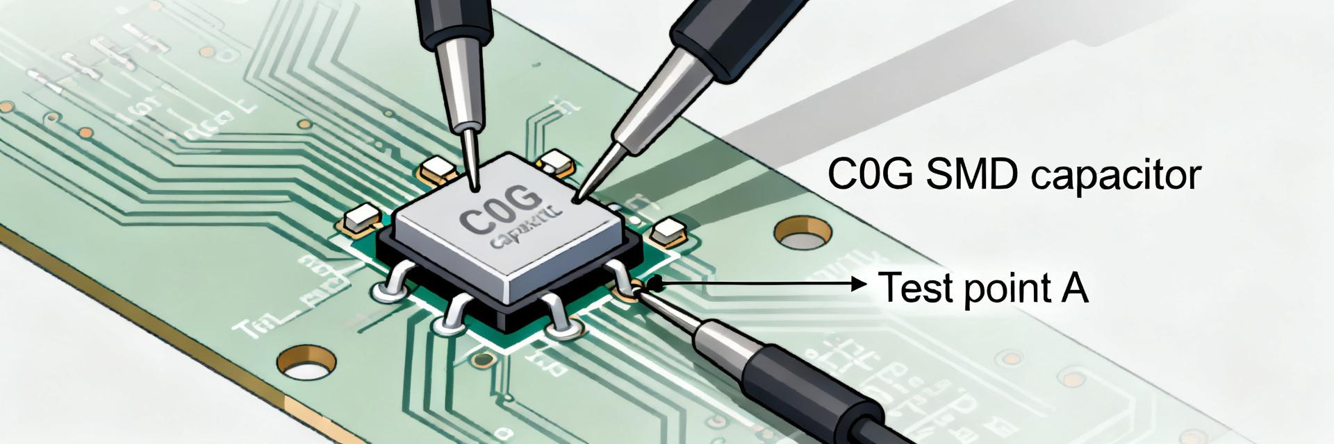
Point: Define clear electrical and inspection criteria to classify failures. Evidence: Use LCR thresholds (open circuit, >20% capacitance drift, ESR rise) and periodic SEM/visual inspection cadence. Explanation: Combined electrical and physical criteria enable mapping of symptom to mechanism and allow Weibull fitting with confidence intervals; recommended sample sizes of 30–60 per condition capture low-PPM modes meaningfully.
Case study — PCB flex & thermal cycling on 0603 2700pF 100V samples
Experiment summary and key results
Point: A controlled comparison showed pad geometry impacts failure rate materially. Evidence: Pad design A (large overhang) recorded ~3.8% failures after 300 cycles; Pad design B (reduced overhang, chamfered pads) showed ~0.7% failures same run. Explanation: The differential implicates edge tensile stress from overhangs as primary driver; improvements are reproducible across boards.
Root-cause analysis and lessons learned
Point: Failures traced to mechanical strain concentration and aggressive reflow. Evidence: Visual/SEM inspection revealed edge cracks initiating near terminations correlated to stiff fillets and rapid ramp profiles. Explanation: Mitigations that reduce solder stiffness, refine pad geometry, and moderate reflow ramps effectively translate to measurable failure-rate reductions on comparable PCB stackups.
Design-for-reliability checklist — PCB layout, assembly & specification guidance
Immediate layout and assembly mitigations
Point: Practical layout changes lower risk quickly. Evidence: Do: reduce pad overhang, use chamfered pads, encourage fillet wetting; Don't: use large stiff fillets or place MLCCs across board splits. Explanation: Implementing keep-out zones, modest solder volumes, and localized board stiffeners where needed cuts mechanical load transfer to the ceramic body.
Specification, sourcing and test recommendations
Point: Part selection and qualification close the loop on reliability. Evidence: Specify dielectrics with balanced reliability vs density, request generic manufacturer reliability summaries, and require sample production runs with thermal/flex screening. Explanation: When high capacitance in 0603 is unavoidable, consider soft-termination constructions, larger case sizes, or in-line LCR sampling to monitor lot-level shifts.
Summary
MLCC 0603 2700pF 100V failure rates vary by environment, commonly driven by board flex, CTE-driven thermal cycling, and assembly stress. Top immediate mitigations are optimized pad geometry, controlled reflow profiles, and selecting termination or part forms that reduce stress transfer to the ceramic. Prioritize targeted tests on your PCB stackup using the checklist above.
Key Summary
- MLCC in 0603 with 2700pF and 100V rates cluster from ~0.5%–4% under moderate stress; cracking from board flex and stiff fillets is the dominant failure mechanism—change pad geometry and solder volume first to reduce risk.
- Accelerated lab tests (thermal cycling and flex) plus Weibull analysis convert findings into field-life estimates; run 30–60 samples per condition for meaningful low-PPM statistics and use combined electrical and visual failure criteria.
- Design steps: reduce pad overhang, encourage compliant fillets, moderate reflow ramps, and consider soft-termination or larger packages when density permits; implement in-line LCR spot checks during production acceptance.
FAQ
How does board flex affect MLCC failure rate?
Board flex produces tensile and compressive strain concentrated at chip edges; evidence from bend tests shows higher failures with overhang pads and stiff solder fillets. Reducing pad overhang, using chamfered pads, and limiting solder stiffness shifts strain away from the termination and lowers crack initiation likelihood.
Are 0603 2700pF 100V parts more failure-prone than larger packages?
Yes—higher capacitance in small 0603 packages increases brittleness and crack susceptibility under mechanical or thermal stress. Larger case sizes or soft-termination constructions absorb more strain, so when layout allows, choosing a larger footprint or a termination designed for compliance improves reliability.
What are minimal test steps to qualify assemblies for MLCC reliability?
Run an initial matrix with representative pad variants, 30+ samples per condition, and accelerated thermal cycling plus controlled board-bend tests. Use electrical thresholds (open, >20% drift) and periodic visual/SEM inspection; fit Weibull curves to accelerated data to estimate field-equivalent life and set production acceptance criteria.
What design mitigations prevent thermal reflow-induced cracking?
Slower thermal ramp rates during reflow, maintaining controlled peak temperatures, and optimizing local thermal gradients across densely populated boards significantly reduce thermomechanical shock and micro-crack nucleation.