Cross-referencing the official datasheet with bench measurements shows how the GMT10X7R822K50NT4 performs under real-world DC bias, frequency and temperature conditions — information essential for reliable power-rail decoupling and filter design. This report summarizes the part-id decoding, the electrical specs engineers must check, a compact datasheet-summary table, recommended test procedures, representative bench-data formats, and actionable selection and troubleshooting steps.
1 — Part ID & Background: Decoding GMT10X7R822K50NT4

Part-number breakdown
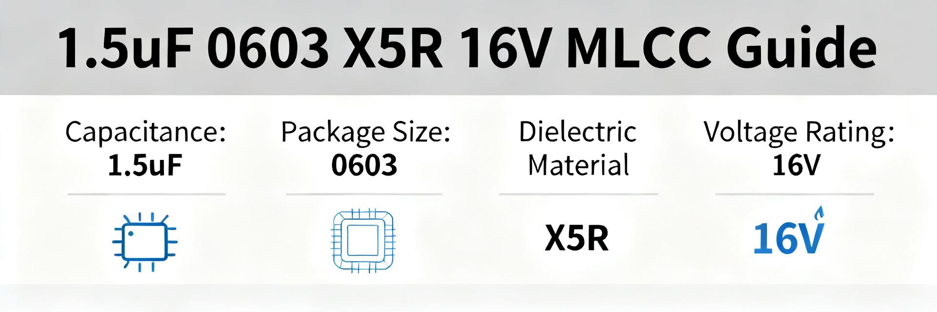
The GMT10X7R822K50NT4 part-number encodes capacitance, tolerance, dielectric, voltage rating and package. Parse it as: series prefix (GMT), dielectric family (X7R), capacitance code “822K” → 8200 pF ±10%, rated voltage “50” → 50 V, package code “NT4” → 0603 (1608 metric) typical. Always confirm the mapping against the manufacturer datasheet; this ensures the listed capacitance, voltage and package match the physical part, and avoids substitutions that alter performance.
Key datasheet fields engineers must check
Essential specs to verify before selection include nominal capacitance, tolerance, rated voltage, dielectric temperature coefficient and operating temperature range. Electrical items: capacitance vs frequency, capacitance vs DC-bias, impedance/ESR/tanδ, and leakage current/insulation resistance. Mechanical/reliability: solder profile, moisture sensitivity level, mechanical strength and available lifetime or reliability data. These fields determine effective capacitance in-circuit and long-term stability under assembly and field conditions.
2 — Complete Electrical Specs & What They Mean for Design (GMT10X7R822K50NT4)
Datasheet spec table to include
Provide a concise table showing nominal and test-condition values with units and min/typ/max columns so designers can read effective performance at a glance. Report the standard test frequency and voltage used by the datasheet, and annotate any disclaimers about DC-bias or temperature test points.
| Parameter | Typical | Min/Max | Units / Notes |
|---|---|---|---|
| Nominal capacitance | 8200 | ±10% | pF |
| Dielectric | X7R | — | ±15% -55→+125°C |
| Rated voltage | 50 | — | V DC |
| Package | 0603 | 1608 metric | SMT |
| Test freq / voltage | 1 kHz / 0.5 Vrms | — | Annotate per datasheet |
| Leakage | — | As specified | µA at rated V |
Interpreting key specs for system behavior
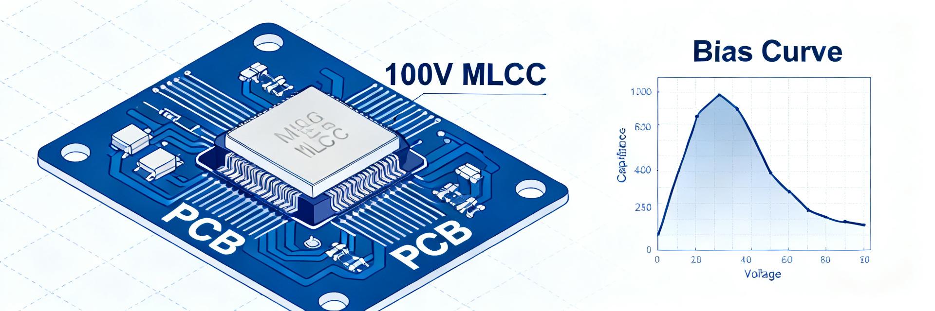
X7R dielectrics show significant DC-bias capacitance reduction: under moderate DC voltages a 0603 X7R 8200 pF part can lose 30–60% of capacitance depending on thickness and construction. Designers must derate for tight decoupling margins or choose higher nominal capacitance. Frequency dependence also matters: capacitance and impedance vary with frequency; an LCR reading at 1 kHz may not reflect behavior at MHz switching frequencies used in decoupling scenarios.
Temperature and mechanical stress further change effective capacitance. X7R is rated for −55 to +125°C with typical ±15% excursion, but real parts can drift outside lab conditions. When precise time-constant or filter performance is needed, consider C0G/NP0 or larger packages despite lower density.
3 — Test Setup & Bench Data: How to Measure the GMT10X7R822K50NT4
Recommended test procedures and equipment
Use an LCR meter (1 kHz and 100 kHz) for spot checks and an impedance analyzer for wideband response up to tens of MHz. Measure leakage with a source-meter at rated voltage. For thermal behavior, use a temperature chamber covering −40°C to +85°C and at least up to +125°C if available. Report fixture details and open/short calibration; test N ≥ 5 samples and report mean ± standard deviation for repeatability.
Report format & critical measured metrics
Publish measured capacitance at each frequency and DC-bias point, percent change vs nominal, impedance vs frequency, ESR/tanδ vs frequency, and leakage at rated voltage. Provide plots for Capacitance vs DC-bias, Impedance vs Frequency, and Capacitance vs Temperature. Include pass/fail guidance: if capacitance at operating DC-bias is below required effective value by more than design margin (typical margin 20–30%), up-rate the capacitor or choose alternate dielectric.
| Metric | Test points | Report |
|---|---|---|
| Capacitance@freq & DC-bias | 1 kHz, 100 kHz; 0→10→25→50 V | Mean ± stddev, % of nominal |
| Impedance | 10 kHz–10 MHz | |Z|(f) plot |
| ESR / tanδ | 1 kHz–1 MHz | Values vs freq |
| Leakage | Rated V | µA, mean ± stddev |
4 — Application Examples & Comparative Benchmarks (case studies)
Typical application scenarios for an 8200 pF X7R 50 V, 0603 capacitor
An 8200 pF X7R in 0603 is well-suited for mid-voltage power-rail decoupling (e.g., analog rails, 12 V systems with point-of-load regulation), EMI/RFI filtering, and AC coupling where high capacitance density is required. Place parts close to the IC, minimize loop area with vias and short traces, and pair with low-ESR bulk capacitors for broadband decoupling. Use star routing or stitched ground to control return currents.
Benchmarks vs alternatives (what to compare and why)
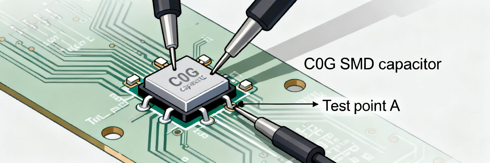
Compare measured DC-bias loss to a C0G/NP0 equivalent to quantify stability trade-offs: C0G offers near-zero bias drift but much lower capacitance per case. If measured DC-bias reduction leaves insufficient effective capacitance, choose a larger package or different dielectric. Benchmarks should include capacitance retention at operating bias and impedance at switching frequency to guide dielectric selection.
5 — Selection, Qualification & Troubleshooting Checklist
Pre-selection checklist for engineers
- Verify effective capacitance at operating DC bias/frequency using Capacitance vs DC-bias curve.
- Confirm 0603 footprint compatibility with assembly and power handling.
- Check reflow profile and moisture sensitivity; plan baking if MSL requires.
- Document required reliability and compare manufacturer lifetime data for target application class.
On-board test & failure-mode troubleshooting
Detect failures via visual inspection (cracks), continuity tests (open/short), and in-circuit impedance/capacitance checks. Typical failure causes include mechanical cracking from board flex, thermal shock during reflow, compromised solder joints and accelerated aging. Mitigations: increase margin by using higher nominal capacitance, adopt C0G for critical filters, change footprint, or adjust assembly profile to reduce thermal/mechanical stress.
Summary
- Datasheet essentials: confirm nominal 8200 pF ±10%, X7R dielectric, 50 V rating and 0603 package; check capacitance vs DC-bias and frequency before final selection.
- Test plan: measure C@1 kHz/100 kHz and across 0→50 V DC-bias, impedance vs frequency and leakage; report mean ± stddev for N≥5 samples.
- Design guidance: account for 30–60% DC-bias loss in X7R 0603 parts for decoupling; consider larger packages or C0G for stability-critical circuits.
- Deliverables recommended: datasheet-summary table, sample measurement table, and three plots (Capacitance vs DC-bias; Impedance vs Frequency; Capacitance vs Temperature) for design reuse.
6 — Common Questions and Answers
What is the effective capacitance of GMT10X7R822K50NT4 under DC bias?
Measure capacitance across the DC-bias sweep; typical X7R 0603 parts of this nominal value can show 30–60% reduction at high bias. Report mean ± stddev for N≥5; if effective capacitance at operating bias is below requirement by more than 20–30%, choose higher nominal value or alternate dielectric.
How should GMT10X7R822K50NT4 be qualified for power-rail decoupling?
Qualification should include capacitance vs DC-bias and temperature, impedance profile across switching frequencies, leakage at rated voltage, solderability/reflow cycle tests and MSL handling. Run N≥5 samples and include thermal cycling if application requires elevated reliability levels.
What troubleshooting steps isolate failures of GMT10X7R822K50NT4 in-circuit?
Start with visual inspection and continuity. Perform in-circuit impedance or capacitance checks, then isolate by removing the part if practical. Check solder joints and surrounding layout for mechanical stress. If cracking or open circuits are found, revise footprint, assembly profile, or select a more robust dielectric/package.
What key datasheet fields must engineers check to verify GMT10X7R822K50NT4 stability?
Essential parameters to verify include nominal capacitance, tolerance, rated voltage, dielectric temperature coefficient, operating temperature range, impedance/ESR/tanδ, leakage current/insulation resistance, solder profile, moisture sensitivity level, and mechanical strength.