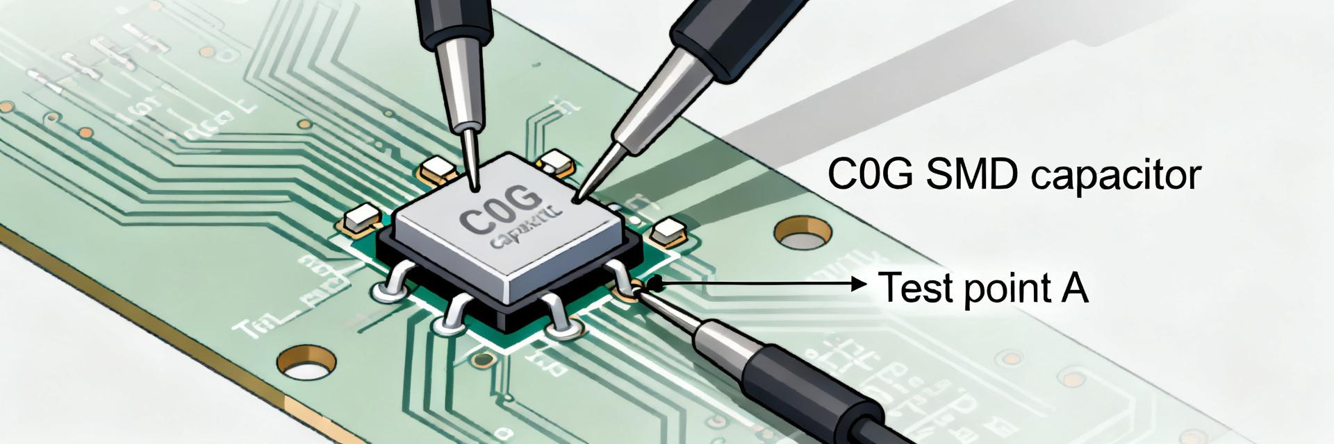
Snapshot: The GMT10X7R222K50NT4 decodes to a 2,200 pF (2.2 nF) MLCC with a ±10% (K) tolerance and 50V rating. Utilizing the Class II X7R dielectric, it offers a balance of stability and volumetric efficiency, though it requires careful DC bias derating in high-density decoupling roles.
| Parameter | Specification | Condition/Note |
|---|---|---|
| Nominal Capacitance | 2.2 nF (2200 pF) | Measured at 1 kHz, 1.0±0.2 Vrms |
| Tolerance | ±10% (K Code) | Industry standard for Class II |
| Rated Voltage | 50 VDC | Derating recommended for DC bias |
| Dielectric | X7R | -55°C to +125°C (ΔC: ±15%) |
| Dissipation Factor | ≤ 2.5% | At 1 kHz, 20°C |
(1) Datasheet Field-by-Field Breakdown
1.1 Understanding the Part Code
GMT10X7R222K50NT4 is a structured identifier. The "222" signifies 22 followed by two zeros in pF; "X7R" defines the temperature coefficient; and "50" marks the maximum DC voltage. For engineers, this code immediately signals that capacitance will drop under applied voltage—a critical factor in 24V or 48V rail decoupling.
(2) Electrical Performance & Bench Tests
2.1 DC Bias and Temperature Sensitivity
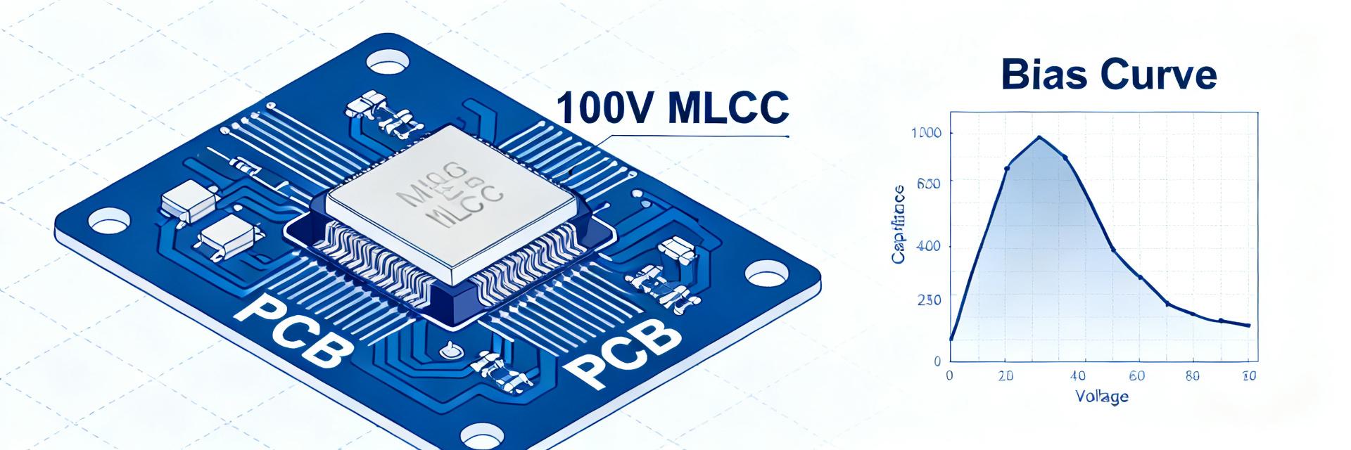
X7R dielectrics exhibit non-linear behavior. At 50% of rated voltage (25V), the GMT10X7R222K50NT4 may see a 15-25% reduction in effective capacitance. Bench testing should involve an LCR meter with a DC bias source to map the C-V curve, ensuring the remaining capacitance meets the system's ripple requirements.
2.2 Impedance and ESR Validation
The Equivalent Series Resistance (ESR) impacts filtering efficiency. Using an impedance analyzer, sweep from 1 MHz to 1 GHz. The Self-Resonant Frequency (SRF) should be identified to ensure the capacitor acts as a capacitive element rather than an inductive one at the target switching frequency.
(3) Application & Reliability Guide
3.1 Layout and Solderability
Place the component as close to the IC power pins as possible to minimize parasitic inductance. Ensure the land pattern matches the NT4 suffix specifications (typically 0603 or 0805 size depending on series) to avoid "tombstoning" during reflow. Mechanical stress tests, such as board flexure tests, are vital for X7R parts due to their ceramic brittleness.
Key Summary
- Nominal vs. Effective: 2.2nF is the zero-bias value; expect significant loss at 50V.
- Thermal Range: Stable from -55°C to +125°C, making it suitable for industrial environments.
- Test Protocol: Always include DC bias sweeps and ESR measurements in your validation report.
Frequently Asked Questions
What should be verified first on a GMT10X7R222K50NT4 datasheet?
Verify nominal capacitance, rated voltage and expected working voltage (derating), and the datasheet’s conditions for capacitance measurement (frequency, temperature, and DC bias). These determine whether the part delivers required effective capacitance in the target application.
How much capacitance loss under DC bias is typical for an X7R capacitor?
Typical X7R parts can lose roughly 10–40% capacitance under moderate DC bias depending on dielectric thickness and stack. Measure the DC bias curve at your operating voltages and document acceptable deltas for the application to set design margins.
Which bench tests confirm GMT10X7R222K50NT4 suitability for production?
Run an impedance sweep, ESR extraction at operating frequencies, DC bias capacitance curve, temperature sweep, and a ripple current endurance test. Include mechanical stress checks (reflow, shear) and report pre/post electrical values with uncertainty to validate lot acceptance.
How does termination type affect GMT10X7R222K50NT4 reliability?
Standard terminations are prone to cracking under board flex; verify solderability and perform shear tests to ensure mechanical integrity in high-vibration environments. The "NT4" suffix often denotes specific plating or tape-and-reel specs that influence assembly yield.